Chopper (Flip Flop) Relays
Redarc Chopper relays have two outputs which operate alternately with the application of inputs (+12V or +24V) from a single, momentary action, push-button switch.
CR1224 Whilst the button is pressed and for approximately ¼ second after release, one output supplies 12V or 24V (depending on supply voltage). Next time the button is pressed, the other output operates, in the same way.
CR1224L An output remains on (latched) until the next input signal causes the outputs to swap. The outputs are either +12V or +24V, depending on the supply voltage.
RATINGS
Chopper relays can be operated in either a 12V or a 24V negative ground system. Each output has a maximum rating of 10 AMPS - the supply must be protected by a fuse of suitable rating.
CONNECTIONS
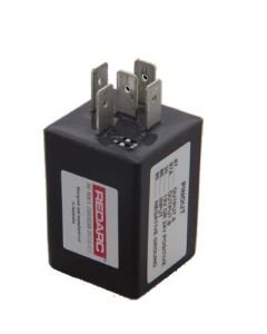
Chopper relays are assembled with 5 pins arranged in a standard automotive change-over relay configuration and can be plugged into a standard relay socket.
The connections shown below are the relay pins as viewed looking at the pin end of the relay (not looking into the relay socket):
 Pin 87……OUTPUT A
Pin 87a…..OUTPUT B
Pin 30……12V OR 24V SUPPLY
Pin 86……POSITIVE INPUT
Pin 85……NEGATIVE GROUND
-
 Redarc Latching 'Chopper' Relay (Flip-Flop)Special Price $198.00 Regular Price $209.00

